Tuesday 28 January 2014

D.C Motor control Using Touch Screen.

How to wok TFT or Touchscreen?
A touch panel is a thin, self-adhesive transparent panel placed over the screen of a graphic LCD. It is very sensitive to pressure so that even a soft touch causes some changes on output signal. 


Principle of operation:
A resistive touch panel consists of two transparent rigid foils, forming a “sandwich” structure,that have resistive layers on their inner sides. The resistance of these layers usually does not exceed 1Kohm. The opposite sides of the foils have contacts available for use through a _at  cable. The process of determining coordinates of the point in which the touch panel is pressed can be broken up into two steps. The _rst one is the determination of the X coordinate and the second one is the determination of the Y  coordinate of the point. In order to determine the X coordinate, it is necessary to connect the left contact on the X surface to ground and the right contact to the power supply. This enables a voltage divider to be obtained by pressing the touch panel. The value of the divider is read on the bottom contact of the Y surface. Voltage can be in the range of 0V to the power supply and depends on the X coordinate. If the point is closer to the left contact of the X surface, the voltage will be closer to 0V. In order to determine the Y coordinate, it is necessary to connect the bottom contact on the Y surface to ground, and the upper contact to power supply.
 
Connecting to micro controller(PIC18F):


 Hardware Description:
Microcontroller used PIC18F458
VCC=5V
GND=0V
CRYSTAL USED 8 MHz

//////////////////////////////////////////////////////
////////PIN DESCRIPTION OF PIC18F458/////////////////
////////////////////////////////////////////////////
PIN1:  RESTART OF MICROCONTROLLER
PIN2:  READ X(TFT) A/D
PIN3:  READ Y(TFT) A/D
PIN4:  ANALOG CONVERSION (VREF(-) USED AS GND)
PIN5:  ANALOG CONVERSION (VREF(+))
PIN6:  SENSOR(S3)
PIN7:   SENSOR(S1)
PIN8:   SENSOR(S2)
PIN9:
PIN10:
PIN11:   VCC(+5V)
PIN12:   GND(GND)
PIN13:   XT (CRYSTAL OSCILLATOR) USED 8 MHz
PIN14:   XT (CRYSTAL OSCILLATOR)
PIN15:   RC0 USED FOR DRIVE A OF TFT
PIN16:   RC1 USED FOR DRIVE B OF TFT
PIN17:
PIN18:  USB VOLTAGE (3.3V)  NC
PIN19:  D0 OF TFT (DATA PORT USING FOR TFT)
PIN20:  D1 OF TFT
PIN21:  D2 OF TFT
PIN22:  D3 OF TFT
PIN23:  INPUT1 FOR H BRIDGE1
PIN24:  INPUT2 FOR H BRIDGE1
PIN25:  INPUT1 FOR H BRIDGE2
PIN26:  INPUT2 FOR H BRIDGE2
PIN27:  D4 OF TFT
PIN28:  D5 OF TFT
PIN29:  D6 OF TFT
PIN30:  D7 OF TFT
PIN31: GND (0V)
PIN32: VDD(+5V)
PIN33: CS1 OF TFT
PIN34: CS2 OF TFT
PIN35: RS OF TFT
PIN36: R/W OF TFT
PIN37: ENABLE OF TFT
PIN38: RST OF TFT
PIN39:
PIN40:
//////////////////////////////////////////////////////////
////////// DESCRIPTION OF TFT TOUCH PANEL////////////////
////////////////////////////////////////////////////////
 ////////IN GENERAL CONFFIGHRATION OF RESISTIVE TOUCH PANEL////////
PIN1: CS1 CONNECTED  WITH RB0
PIN2: CS2 CONNECTED  WITH RB1
PIN3: GND
PIN4: VCC
PIN5: VO
PIN6: RS(REGISTER SELECTION) CONNECTED  WITH RB2
PIN7: R/W(READ OR WRITE) CONNECTED  WITH RB3
PIN8: ENABLE CONNECTED  WITH RB4
PIN9: D0 CONNECTED  WITH RD0
PIN10: D1 CONNECTED  WITH RD1
PIN11: D2 CONNECTED  WITH RD2
PIN12: D3 CONNECTED  WITH RD3
PIN13: D4 CONNECTED  WITH RD4
PIN14: D5 CONNECTED  WITH RD
PIN15: D6 CONNECTED  WITH RD6
PIN16: D7 CONNECTED  WITH RD7
PIN17: RST(RESTART) CONNECTED  WITH RB5
PIN18:  VEE
PIN19:  LED(+) VCC
PIN20:  LED(-) GND
RIGHT(1): RIGHT SHIFT  CONNECTED WITH RC0 DRIVE A
TOP(2): TOP SHIFT  CONNECTED WITH RC0 DRIVE A
LEFT(3): LEFT SHIFT  CONNECTED WITH RC0 DRIVE A
BUTTOM(4):BUTTOM SHIFT  CONNECTED WITH RC1 DRIVE B
DRIVE A:  CONNECTED WITH RC0
DRIVE B:  CONNECTED WITH RC1
READ  X:  READING X (DRIVEA = 1 (LEFT drive on, RIGHT drive on, TOP drive off ) , DRIVEB = 0 (BOTTOM drive off ),reading X value from RA0/ANO (BOTTOM))
REDY  Y:  READING Y (DRIVEA = 0 (LEFT drive off , RIGHT drive off , TOP drive on), DRIVEB = 1 (BOTTOM drive on),reading Y value from RA1/AN1 (from LEFT))
SEE THE PDF FOR UNDERSTANDING THE CONNECTION.
///////////////////////////////////////////////////////
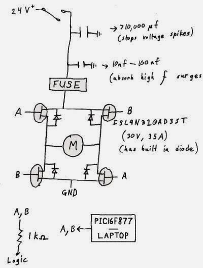
////////// SENSOR MODULE AND H BRIDGE CONNECTION///////
///////////////////////////////////////////////////////

Application :
Here control d.c motor both manual and automatic using Touch Screen.


Programming:
void main() {
unsigned char x;
 TRISD=0x00;
 TRISB=0x00;
 TRISA5_bit=1;
 TRISE0_bit=1;
 TRISA0_bit=1;
 TRISA4_bit=1;
 TRISA1_bit=1;
 TRISC4_bit=0;
 TRISC5_bit=0;
 TRISC6_bit=0;
 TRISC7_bit=0;
 TRISC1_bit=0;
 TRISC0_bit=0;
 TRISB6_bit=1;
 GLCD_CS1 = 1; // De-Activate both chips
 GLCD_CS2 = 1;
 GLCD_RST = 1;
 GLCD_ON();
 GLCD_Set_Font(Font_Glcd_5x7, 5, 7, 32); // Choose font
 GLCD_Fill(0); // Clear GLCD
 CopyConst2Ram(msg,msg1); // Copy “COUNTER= ” string to RAM
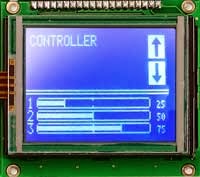
 Glcd_Write_Text(msg,10,0,1);

//Display Buttons on GLCD: ////////

 GLCD_Rectangle(3,10,50,35,1);
 GLCD_Rectangle(7,16,35,45,1);
 GLCD_Rectangle(68,16,120,48,1);
 GLCD_Box(10,18,58,46,1);
 GLCD_Box(70,14,90,44,1);
 GLCD_Box(50,16,70,48,1);
 CopyConst2Ram(msg,msg2); // Copy “BUTTON1” string to RAM
 GLCD_Write_Text(msg,14,3,0);
 CopyConst2Ram(msg,msg4);
  GLCD_Write_Text(msg,14,4,0);
 CopyConst2Ram(msg,msg3); // Copy “BUTTON2” string to RAM
 GLCD_Write_Text(msg,74,3,0);
 CopyConst2Ram(msg,msg5); // Copy “MOTOR ANTICLOCKWISE” string to RAM
 GLCD_Write_Text(msg,74,5,0);
 CopyConst2Ram(msg,msg9); // Copy “BUTTON3” string to RAM
  GLCD_Write_Text(msg,82,3,0);
 CopyConst2Ram(msg,msg6); // Copy “STOP” string to RAM
 GLCD_Write_Text(msg,82,4,0);
Label:
SWITCH1=0;

switch(SWITCH1)
{
case 0:           ////FOR AUTOMOMATIC////

if (S1==1 && S2==1)
MOTOR_CLOCKWISE();
else if(S1==1 && S2==0)
MOTOR_ANTICLOCKWISE();
else if(S1=0 && S2==0)
MOTOR_STOP();
else
MOTOR_STOP();
break;

case 1:                 //////FOR MANNUAL///

if (TP_Press_Detect())
x_coord = GetX();
y_coord = GetY();
x_coord128 = (x_coord * 128) / 1024;
y_coord64 = 64 -((y_coord *64) / 1024);

//if BUTTON1 is selected
if ((x_coord128 >= 10) && (x_coord128 <= 58) && (y_coord64 >= 18) && (y_coord64 <= 46)) {
 {
 {
MOTOR_CLOCKWISE();
CopyConst2Ram(msg,msg7); // Copy “CLOCKWISE  ON “ string to RAM
Glcd_Write_Text(msg,14,4,0);
}

if ((x_coord128 >= 70) && (x_coord128 <= 90) && (y_coord64 >= 14) && (y_coord64 <= 44)){
MOTOR_ANTICLOCKWISE();
CopyConst2Ram(msg,msg8); // Copy “ANTICLOCKWISE ON “ string to RAM
Glcd_Write_Text(msg,74,4,0);
}
if ((x_coord128 >= 70) && (x_coord128 <= 90) && (y_coord64 >= 14) && (y_coord64 <= 44)) {
MOTOR_STOP();
CopyConst2Ram(msg,msg10); // Copy “STOP “ string to RAM
Glcd_Write_Text(msg,74,4,0);
}
else
MOTOR_STOP();
}
}
break;
T0CON=0x68;
TMR0L=0;
if (S1==1){
do{
T0CON.TMR0ON=1;
x=TMR0L;
}
while(INTCON.TMR0IF==0);
T0CON.TMR0ON=0;
INTCON.TMR0IF==0;
}
CopyConst2Ram(msg,msg1);
GLCD_Write_Data(x);
}
if (x=200)       ////8 bit counter so 25 maxima
MOTOR_STOP();
else
goto Label;
}


Thank You.

Saturday 25 January 2014

A Fingertip Identification

The fingerprint identification technique is also termed as “Dactyloscopy” or “Handprint Identification”.A fingerprint in its narrow sense is an impression left by the “friction ridges” of the human digits (hand and foot). However in a wider sense fingerprints can be the impression of the friction ridges of any part of the human hand or human foot.A friction ridge is basically the raised portion of the epidermis layer of the skin. This epidermis layer is much more ‘groovy’ or developed at those parts of the human body that is meant for holding or for gripping, viz. hands and feet. These ridges or grooves are stimulated by the human nervous system. They are caused by the underlying interface between the dermal papillae of the dermis and the inter-papillary pegs of the epidermis.
Since the epidermal layer of the skin is made from the epidermal cells of the body, so obviously, the epidermal ridges of an individual is unique and varies from person to person. These varying epidermal ridges or the grooves are the major tool that distinguishes an individual from another person in the field of fingerprint identification technique.
The impressions of fingerprint are the traditional samples used for going into the fingerprint analysis. These impressions are left behind on objects due friction between the epidermal grooves and the surface of the object. The availability of the fingerprints is well questioned in many cases because they are not present in many cases. However, the technique involves very complex programming of matching the images of two fingerprints. There have been several cases when the fingerprints went missing (say for bomb blast). Besides due continuous use of the sensing plates, they get corroded and may give faulty results. This technique is also cost effective.

Compared to that, the idea of using simple light deflection and measuring the values is much simpler and reduces the complexity of the programming portion and the circuit. They can be used for a long time because the sensor module is resistant to corrosion and heating effects. Also the cost of implementation of the project is low and simple too.

 How our model works:

Step 1:  Data collection (data is collected for any number of people and is stored in the memory of the computer)


The values are obtained just by measuring the voltages at the sensors and amplifying them to bring them into a reasonable range. Then they are converted into digital signal so that they can be stored in the computer. This is the reason for our circuit being so versatile and an infinite user one. It can store any number of data taken from all the human beings of the earth. All the data obtained are distinct because they are related to fingerprint.

           
            Step 2: While matching


       When we want to find a particular person, the 1st step is followed again to obtain the         values. Now this value (which is obviously unchanged for a particular person) is searched from the computer database and we can find the details then.

The programming is very simple and the database can store a huge number of data. The cost is also low compared to the traditional technology of matching fingerprint images.


Friday 24 January 2014

Software Part of PC Based Temperature or multiple Sensor control.

#include<reg52.h>
 #define LINE1 0x80 #define LINE2 0xC0 
#define COLUMN1 0x00
 #define COLUMN2 0x01
 #define COLUMN3 0x02 
#define COLUMN4 0x03
 #define COLUMN5 0x04
 #define COLUMN6 0x05 
#define COLUMN7 0x06 
#define COLUMN8 0x07
 #define COLUMN9 0x08
#define COLUMN10 0x09
 #define COLUMN11 0x0a
#define COLUMN12 0x0b
#define COLUMN13 0x0c 
#define COLUMN14 0x0d 
#define COLUMN15 0x0e 
#define COLUMN16 0x0f
Sbit      LCD_RS=P0^0;

Sbit      LCD_RW=P0^1;

Sbit      LCD_EN=P0^2;

Sbit      LCD_BUSY=P1^7;
Sbit
ADC_RD=P0^5;

Sbit
ADC_WR=P0^4;

Sbit
ADC_CLK=P0^3;

Sfr
ADC_DATA=0X90;

Sfr
LCD_DATA=0x90;

Void
LCD_Data (unsigned char);

Void
LCD_Command (unsigned char);

Void
LCD_Init (void);

Void
LCD_Decimal (unsigned char pos,unsigned char var);

Void
LCD_Hex (unsigned char pos,unsigned char var);

Void
LCD_String (unsigned char,unsigned char *var);

Void
LCD_Int16 (unsigned char pos,unsigned int var,unsigned char n);

Void
LCD_Clear ();

Void
Delay (unsigned int tic);

Unsigned char  ADC0804_Read ();

Void
RS232_Init (int  baudrate);

Void
RS232_String (unsigned char *var);

Void
RS232_Send (unsigned char d);

Unsigned
RS232_Receive ();
Sbit a= P2^0;

Sbit x= P2^1;

Sbit
c=P2^2;

Sbit
e=P2^3;


Void main (void)

{
Unsigned char Val, d, PORT_2; a=0;

x=0;

c=0;

e=0;

BUZZER=0;

LCD_Init ();

RS232_Init (9600);

LCD_String (0x80,"ADC=");

for (;;)

{

int i=0;
do

{

i++;
                       Delay (50);

Val=ADC0804_Read ();

LCD_Decimal (LINE1+COLUMN5, val);
// LCD_Decimal(LINE1+COLUMN10,y);

d=100; While (d! =0)

{

RS232_Send (val/d+0x30);

Val= val%d;

d=d/10;

}

}

While (i!=5);

RS232_Receive ();

PORT_2=RS232_Receive ();

LCD_String (0xC0,"P2=");

LCD_Decimal (LINE2+COLUMN4,PORT_2);

Switch (PORT_2)

{
case 49: a=~a; x=0;c=0;e=0;Delay(1000);break; case 50:x=~x; a=0;c=0;e=0;Delay(1000);break; case 51:c=~c; a=0;x=0;e=0;Delay(1000);break; case 52:e=~e; a=0;x=0;c=0;Delay(1000);break; case 53:a=0; x=0;c=0;e=0;Delay(1000);break;

}
}
}


Visual basic:

What a GUI??

GUI is stand for Graphical User Interfaces .It allows for interaction with a computer or other media formats which employ graphical images, special graphical element devices and along with text to represent the information and actions available to a user. GUI allow handling any actions like a mouse click, user enter the data and keystrokes. There was a lot of software to develop a GUI. For example, Visual Basic allow a designer to develop GUI application as a monitoring and controlling system , database application for business and education , games software and more applications.

What a Visual Basic??

VISUAL BASIC is a high level programming evolved from the earlier DOS version called BASIC. In Visual Basic programming is done in a graphical environment. In Visual Basic, the GUI also involves in certain action such as interrupts, timers, serial communication, user control and more actions.

Serial Communication in Visual Basic-

Visual Basic can be used to access serial communication function. -Allow hardware part communicate between GUI for several application like monitoring and control process

Communication Control in Visual Basic

Visual Basic allow many additional components to be add in the toolbox. In order to used serial communication, the Microsoft Com components add to toolbox for transmit and receive data from hardware

Visual Basic used in PC-Based Temperature Control

-This project objective is to use PC-Based for monitor and control the temperature. It means that, the GUI developed should have the text or graphic to show current temperature and the fan status information.

-Visual Basic is used to construct A GUI for temperature monitoring and control. As i mention before, A Visual Basic allow a hardware communicate between computer by using serial communication.

-According to this project, the hardware refer to 8051

Microcontroller communicates between a GUI to display temperature value.
Step t hat have been used in building a GUI:

Step 1: Design the interface


Step 2: Set Properties of the controls (Objects)


Step 3: Write the events' procedure


Advantages:
If we compare a simple 8051 based temperature control with PC based temperature control technique then we got that pc based temperature control technique is an more efficient and have an some advantages.
_ Calibration: Calibration is the most important characteristic in any type of instrument. In this project we can easily calibrate by simply language program. We set any desired value and determine if it has any error then we adjust the value or eliminate the error by using programming, no hardware adjusting needed.
_ Graphical Representation: We are used graph for better understanding to solve and minimize the error. Here we plot a curve in between the output value of temperature sensor LM35 and time. 
Disadvantages: 

Generally every instrument has some advantage and disadvantage also. The disadvantages are following:

   Here we used serial port as a connecting wire; if we used USB (universal serial bus) port then we increase the baudrate in between sending and receiving.


   In this system if any problem occurred that means power off or other type of problem faced then the software not work means again start the software. 
Conclusion:


   There are a few test that have be done in completing this project in order to have accurate data and value to be display at PC. There are temperature sensor tests, A/D converter test, RS232 test and complete project test.

   As a conclusion, the project was aim the objective to measured temperatures in several location then display at computer besides, success to develop a GUI by using Visual Basic for temperature monitoring and control.

Future Improvement: In the future, this project can make several improvements in order to add another feature such as using a wireless to communicate between sensor and microcontroller, monitor and control the temperature via internet and using USB for communication between microcontroller and computer. For graphical User Interfaces, add the function to show real time graph between temperature and time. Then add some features to store all data measured as user reference.